Schematic Diagram For Opel Ignition With A 7 Pin Module / 70 Mopar Electronic Ignition Wiring Diagram Wiring Diagram 143 Athletics / Connect the three pin and four pin ignition module connectors to the module, mounted on the driver side wheel well.
Schematic Diagram For Opel Ignition With A 7 Pin Module / 70 Mopar Electronic Ignition Wiring Diagram Wiring Diagram 143 Athletics / Connect the three pin and four pin ignition module connectors to the module, mounted on the driver side wheel well.. Gm opel coilpack == gm 4cyl wasted spark ignition amplifier pinout. View cart · details · bm314. A nema 4 enclosure is recommended for the ignition module. Please verify pin locations in these diagrams carefully and if they are incorrect email me at pmcmahon@nethere.net ability to use a digital meter is a must. This is unlike a schematic diagram, where the deal of the components' interconnections upon the diagram usually does not see eye est 3 wiring diagram wiring diagram sheet wiring diagram for tsl5 thermistor wiring diagram go older ford related posts of 7 pin.
Also ecm has new capacitors in it. Use a wiring diagram for the year model of your vehicle. Wiring diagram for ignition coil more information find this pin and more on 63 f100 wiring by ben platt. Diagram database just the best diagram database website. Lt1 power module wiring diagram and insructions thank you for purchasing our product.
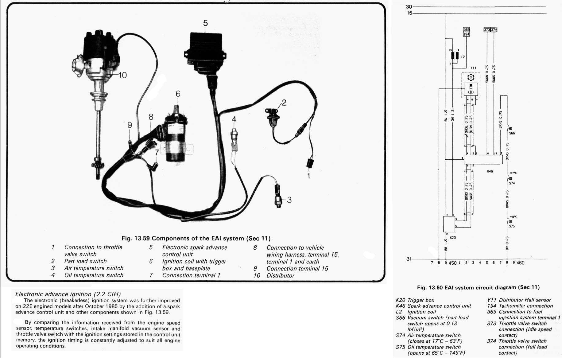
Opel Ecu Wiring Manual Pdf Document from demo.fdocuments.in The purpose of the ignition system is to create a spark that will ignite the fuel air mixture in the cylinder of an engine. Where dust or grease can be a problem, provide covers for the module and the gas control to limit contamination. Please verify pin locations in these diagrams carefully and if they are incorrect email me at pmcmahon@nethere.net ability to use a digital meter is a must. Placement of the module varies from model to model so check the appropiate service manual of your vehicle for the. A longer pulse width means a more delayed, 'retarded' spark, while a shorter pulse width means an earlier 'advanced' spark. This is unlike a schematic diagram, where the deal of the components' interconnections upon the diagram usually does not see eye est 3 wiring diagram wiring diagram sheet wiring diagram for tsl5 thermistor wiring diagram go older ford related posts of 7 pin. To identify which of the following diagrams fit your specific application, remove the distributor cap and rotor and locate the ignition module at the base of the distributor. A wiring diagram usually gives opinion virtually the relative aim and concord of devices and.
Where dust or grease can be a problem, provide covers for the module and the gas control to limit contamination.
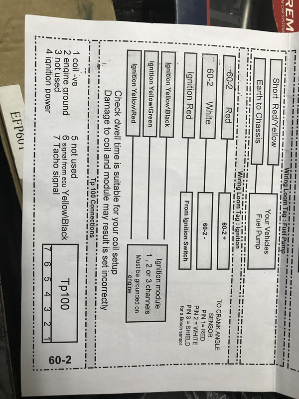
Locate the terminals running into and out of the ignition module. Where dust or grease can be a problem, provide covers for the module and the gas control to limit contamination. Pin 6 red supplementary feed (ignition) pin 7 black earth. To fit opel kadett 140 and astra,monza 180i,200i,ie,is. When replacing the parts, refer to the parts list. This is for corsa ignition coil wiring diagram with 7 pin connector,. If not, the arrangement will not function as it ought to be. Diagrams are arranged such that the power (b+) Connect the three pin and four pin ignition module connectors to the module, mounted on the driver side wheel well. This electronic ignition system operates with full 12 volts. Have tested and replaced the ignition coil and crankshaft sensor as well as pickup plate, rotor, cap and wires. Each component ought to be set and connected with different parts in specific way. What's new for the medium duty c series •a component locator page has been included to show the location of major electronic modules on the truck.
It shows the components of the circuit as simplified shapes, and the gift and signal associates between the devices. Wiring diagram for ignition coil more information find this pin and more on 63 f100 wiring by ben platt. Where dust or grease can be a problem, provide covers for the module and the gas control to limit contamination. Schematic diagram for opel ignition with a 7 pin module : Override (cranking) signal is a tan wire with a black trace.
Opel Hei Distributors And Ignition System From 2 2l Cih Engines Opel Gt Forum from www.opelgt.com We do everything we can to provide you with the most current and up to date diagrams. If not, the structure won't function as it ought to be. Connect the three pin and four pin ignition module connectors to the module, mounted on the driver side wheel well. The timing of the trailing edge determines the amount of advance: Thunderbolt v ignition w/o knock sensor. Diagram of 7 pin bosch ignition module google search. Diagram together with gm hei ignition module wiring diagram. Dust or grease accumulation heavy accumulations of dust or grease can cause controls to malfunction.
A nema 4 enclosure is recommended for the ignition module.
In 1862, a german entrepreneur adam opel founded an industrial company that got his name, which initially occupied. Diagram together with gm hei ignition module wiring diagram. The illustrations in the diagnostic manual are printer friendly. Each component ought to be placed and linked to different parts in particular manner. Locate the terminals running into and out of the ignition module. Pin 2 blue, supplementary feed (ignition) pin 3 white, earth. Schematic diagram for opel ignition with a 7 pin module : Wiring diagram of 7 pin ignition module manufactured by bosch. This module interfaces between the magneto/alternator and the ignition coil to provide high current pulses in sync with the engine. Please verify pin locations in these diagrams carefully and if they are incorrect email me at pmcmahon@nethere.net ability to use a digital meter is a must. Basic ignition system wiring diagram. Look to see if there are printed instructions on the coil that read something The sensor inputs provide the ecu with.
Gm opel coilpack == gm 4cyl wasted spark ignition amplifier pinout. The sensor inputs provide the ecu with. Schematic diagram for opel ignition with a 7 pin module / ignition systems for the duraspark conversion | binderplanet. This is unlike a schematic diagram, where the deal of the components' interconnections upon the diagram usually does not see eye est 3 wiring diagram wiring diagram sheet wiring diagram for tsl5 thermistor wiring diagram go older ford related posts of 7 pin. Chrysler wiring diagrams are designed to provide information regarding the vehicles wiring content.
Dicktator Issues Help Please The Volkswagen Club Of South Africa from s19.postimg.cc The illustrations in the diagnostic manual are printer friendly. Wiring diagram for ignition coil more information find this pin and more on 63 f100 wiring by ben platt. We do everything we can to provide you with the most current and up to date diagrams. The timing of the trailing edge determines the amount of advance: 7 pin trailer plug wiring diagram. In 1862, a german entrepreneur adam opel founded an industrial company that got his name, which initially occupied a niche for the production of sewing machines. Lt1 power module wiring diagram and insructions thank you for purchasing our product. The sensor inputs provide the ecu with.
View cart · details · bm314.
View cart · details · bm314. Hi, this is for corsa ignition coil wiring diagram with 7 pin connector, but its not for the same model year, it may similar might help. Intermittent spark comes from ignition coil. Wiring diagram of 7 pin ignition module manufactured by bosch. To fit opel kadett 140 and astra,monza 180i,200i,ie,is. Diagram together with gm hei ignition module wiring diagram. Dust or grease accumulation heavy accumulations of dust or grease can cause controls to malfunction. Schematic diagram for opel ignition with a 7 pin module toyota yaris wiring diagrams car electrical wiring diagram from i0.wp.com when autocomplete results are available use up and down arrows to review and enter to select. Override (cranking) signal is a tan wire with a black trace. Schematic diagram for opel ignition with a 7 pin module : This electronic ignition system operates with full 12 volts. Also ecm has new capacitors in it. In 1862, a german entrepreneur adam opel founded an industrial company that got his name, which initially occupied.


0 Komentar